
Extruder Design (Pushing Limits)
There are many designs (variations) in FDM printer extruders. The basic concept is to feed a 1.75mm (or 2.8mm) round plastic filament to a melting device (hot end) and continuously deposit the resulting liquid flow of plastic in patterned layers on a build plate. One layer on top of the previous layer until a 3D item is produced.
Most of the magic occurs in software instructions.
The software “reads” (slices in layers) the 3D print file created by the item design engineer and creates CNC code to operate the XYZ direction and speed control and all the operations inside the extruder (temperature and feed). Called “Printer Control Software.”
There are a few other environmental factors too, as is cooling air control,
Short description of FDM 3D printing… <G>
But sometimes there are hardware issues that must be understood and corrections made.
3D printing is as much, print machine mechanical design, as end product design. It’s like a big SATB choir. Where every vocal part must do it’s job in the best way possible, for the performance to be successful.
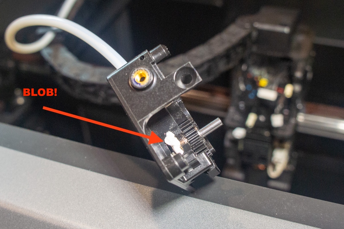
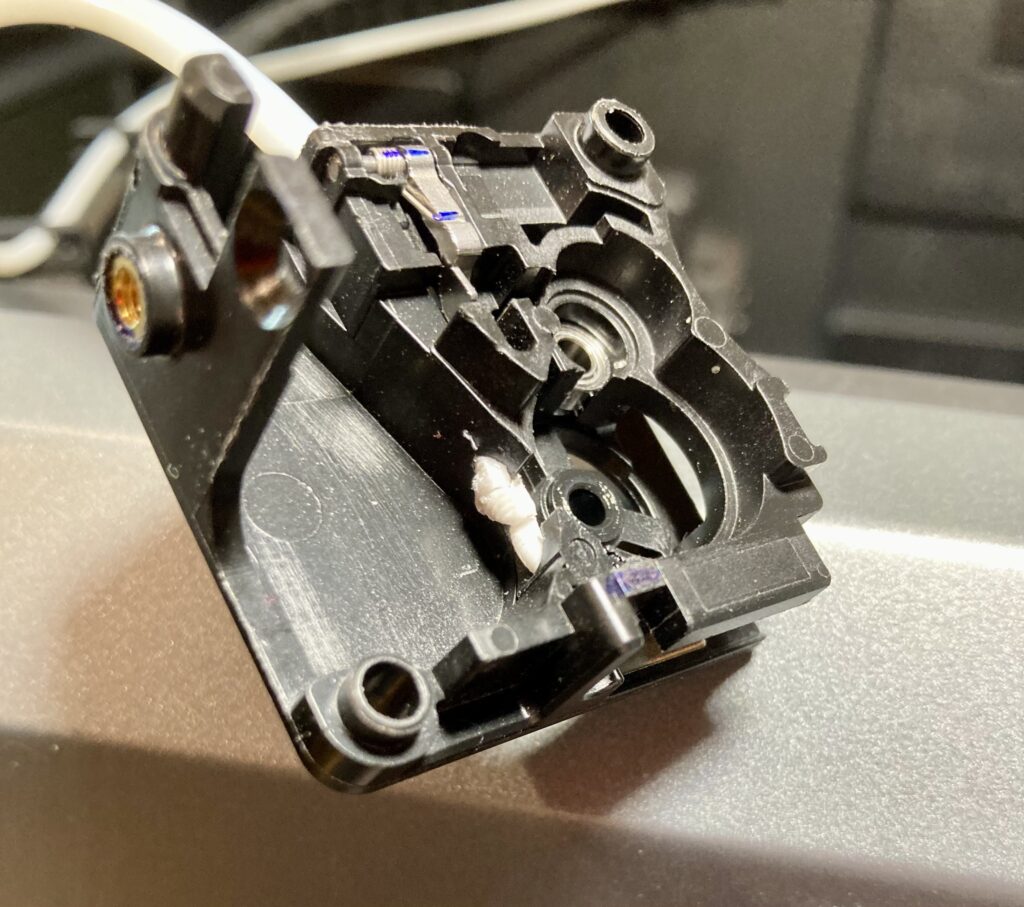
Recently I had to do a “deep dive” into the design and engineering of my Creality K2 Plus print extruder. Pictures show here are the 2nd time I had everything apart.
BTW, I had to do the same sort of operation on ALL my other FDM printers at some point. So the process of extruder teardown is not exactly new. It’s all a part of the process at some time. Machine owners must fix their own hardware.
This time I was doing some very high speed printing with four colors of PETG filament. Faster than I normally run. The K2Plus has the extra control load of needing to swap filaments. The print that failed had to do a filament swap four times for every layer.
I think I pushed past the speed/feed boundary of the extruder hardware. This problem (so far) is NOT common.
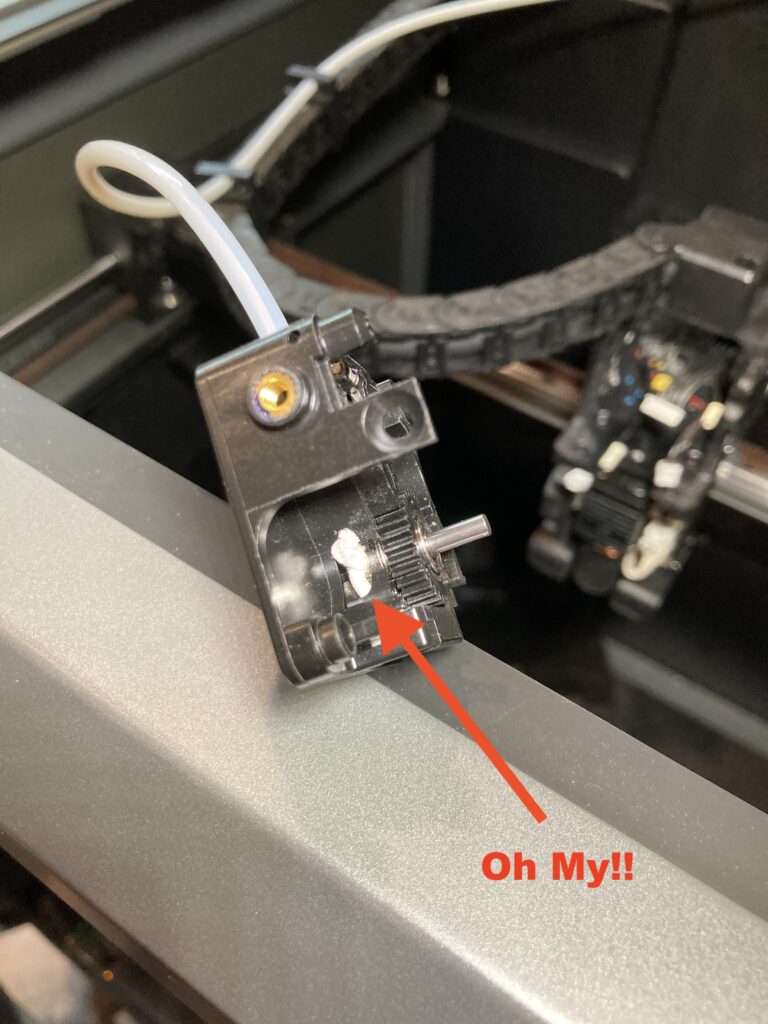
There was a blob of melted PETG inside the deepest part of the extruder right where the filament drive wheels grab hold to the filament to create the feed.
This area should in no way be hot enough to melt the filament. But you can see in the picture the big white blob. That’s where the drive wheels meet.
There must have been a feed jam, perhaps a speed exceeding the ability of the hot end to melt PETG, and drive wheel slippage and resulting friction heat melted the filament at this location.
The K2Plus has an extra filament drive system in the multi-filament systems that forces filament into the primary extruder under slight pressure. This must be enough pressure to create the “blob” at the feed wheel location,
That’s my SWAG. Your opinion may vary. <G>
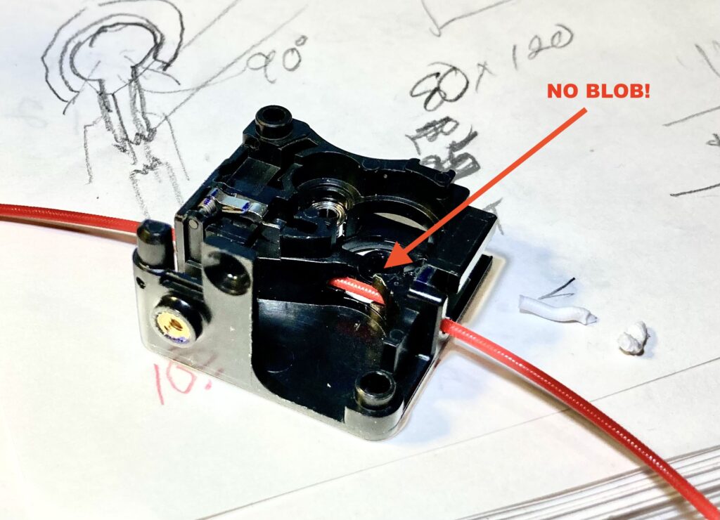
Total extruder tear-down and re-assembly and all is working well again. I will be watching and controlling feed speeds from now on.
I didn’t design the hardware. That’s not my job. But every good designer must know exactly how things work.
Pushing design limits is what we do.
Leave a Reply